
Trevor Ball & N.R. Jenzen-Jones
Overview
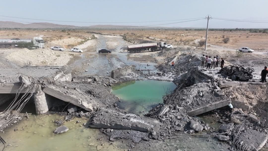
Explosive munitions often leave distinctive physical traces that can provide valuable evidence about the circumstances of an attack. Among the most informative of these traces are craters, which not only preserve evidence of the detonation itself, but may also provide important clues as to a munition’s design, function, fuzing, and method of delivery. By carefully documenting and analysing a crater’s dimensions, shape, orientation, and surrounding damage, investigators can estimate the size of the explosive charge, narrow the range of possible munitions involved, and, in some cases, determine the direction from which the munition was fired. When combined with other forms of physical evidence—such as fragmentation patterns and recovered munition remnants—crater analysis becomes an important component of conflict damage assessment (CDA) and battlefield forensics.
This guide introduces the principles of crater analysis, explains how crater dimensions can be used to estimate explosive charge size, and outlines established techniques for determining the probable firing direction of indirect-fire weapons using crater morphology and other factors. The guide is intended as an introduction to key principles, and is written using only materials that are publicly accessible. A number of more advanced methods and non-public tools are available to specialists, some of which are briefly discussed below. Wherever possible, specialist analysis should be sought to corroborate initial assessments made using the methods presented herein.
What is a Crater?
When conducting a CDA, a typical crater one might encounter results from the impact of a munition and/or its other damage mechanisms. In the context of explosive weapons, the crater results primarily from excavation by the explosion (whether on, above, or below the surface), although the impact itself may also contribute to crater morphology. After a munition detonates, ejecta—material kicked up from the crater site by the explosion—will settle both back inside the crater and around its rim. The ejecta around the edges means that the crater rim is generally higher than the original ground surface, whilst ejecta settling inside the crater can obscure the true depth and radius of the crater. Apparent, or visible, crater radius and depth are often measured and used to estimate the size of the explosive charge that created the crater. The features of a typical crater can be seen in Figure 1a.
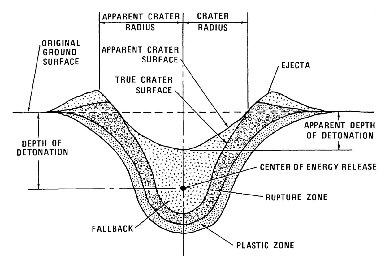
The size of a crater—or indeed whether one is formed at all—is dependent on the amount of explosives contained in a munition, the height from the ground at which it detonates, the power of the explosive composition(s) used, and the ground material(s). Smaller amounts of explosives (smaller charge sizes), a detonation further from the ground, or a more robust ground material (e.g., rock or concrete), can impede the creation of a crater. These factors can result in no significant cratering, or the formation of a smaller crater compared to those formed by larger charge sizes, explosions that occur on contact with the ground, or explosions in sand or light soil. Crater shape can also provide an important source of evidence, and will vary depending on the angle of impact, speed, size, and type of the munition employed. Generally speaking, analysis of the size (volume) of a crater will assist in estimating the quantity of explosive material contained within the munition which caused it, whilst analysing the shape of a crater may assist in identifying the direction from which the munition was delivered.
Estimating Charge Size
Whilst no mathematical model can account for every variable affecting crater formation, empirical formulae developed through explosive testing can provide a useful tool in assessing the relationship between explosive charge weight and crater dimensions. These equations are widely used in military and civilian explosive engineering contexts, and can be used to estimate the apparent crater radius produced by a known explosive charge; or, inversely, to estimate the explosive charge weight from a measured crater radius. The equations below are adapted from Paul W. Cooper’s standard reference text, Explosives Engineering (Wiley, 1996). They are most reliable when applied to conventional high explosive (HE) detonations occurring at or near ground level. To produce meaningful results, the calculations require an assessment of two additional parameters: the Chapman–Jouguet Pressure (PCJ) of the explosive composition and the explosive’s cratering efficiency (ECR) for the relevant soil type. These variables account for differences in explosive performance and ground conditions that significantly influence crater size.
The expected crater size created by an explosive charge of a given weight can be estimated using empirical formulae. A simple formula to this end is provided in Explosives Engineering. The inverse form of this equation can be used to estimate the explosive weight from a measured crater radius.
With Ra indicating the apparent radius of the crater; K indicating the constant 0.46+0.027xPCJ, where PCJ is the Chapman–Jouguet Pressure in Gigapascals (GPa) of the explosive used; ECR indicating the cratering efficiency of an explosive in a given soil medium; and W indicating the explosive weight.
Chapman–Jouguet Pressure can be broadly considered a measure of an explosive composition’s ‘blast power’ (see Table 1); the PCJ varies between compositions due to their differing energetic properties. For a given weight, different explosive compositions will thus vary in power; the precise explosive type should be selected if known, as this provides a more accurate estimate of the expected crater size for a given munition. However, TNT is typically used when the explosive is unknown, and as a standard when comparing explosives.
Table 1 – Chapman–Jouguet Pressure (PCJ) of Selected Explosives
| Explosive Composition | Chapman–Jouguet Pressure (PCJ) in Gigapascals (GPa) |
| TNT | 21 |
| PBXN-109 | 23.7 |
| Pentolite (50/50) | 25.5 |
| Composition C-4 | 25.7 |
| Composition B-3 | 28.7 |
| PETN | 33.5 |
| RDX | 33.8 |
| HMX | 39 |
The ECR, or cratering efficiency of an explosive in a given soil medium, represents the efficiency with which explosive energy is converted into crater excavation in a given soil medium. The higher the ECR value, the larger the crater will be; lower ECR values represent a soil medium that is more resistant to an explosive blast, generally resulting in a smaller crater (see Table 2). Experienced field investigators often report that variations in soil density have the greatest practical influence on the craters produced by comparatively small munitions, such as 60 mm and 81/82 mm mortar projectiles. Larger munitions generally possess sufficient mass and impact energy that they penetrate most natural soil types before functioning, although other factors can still impact crater formation significantly.
Table 2 – HE Cratering Efficiencies for Different Soil Media
| Media | High Explosive Crater Efficiencies (ECR) (ft3/ton) |
| Coral Sand (saturated) | 2 |
| Clay soil/shale (saturated) | 2 |
| Clay soil/shale claystone | 0.95 |
| Glacial soil | 0.75 |
| Clay siltstone | 0.6 |
| Clay soil/shale | 0.55 |
| Alluvium soil (loose clay, silt, sand, or gravel) | 0.5 |
| Sandy clay soil | 0.475 |
| Playa | 0.45 |
| Soil/sandstone | 0.25 |
| Basalt-granite | 0.2 |
Calculator
ARES has developed a simple calculator using Cooper’s formulae—and key underlying data, such as Chapman–Jouguet Pressure (Table 1) and Cratering Efficiency (Table 2)—to simplify crater analysis tasks for researchers. Inputting the radius of a crater will provide an estimated explosive charge weight, whilst inputting an explosive charge weight will provide an estimated crater radius and depth. The depth value is a rough estimate; according to Explosive Shocks in Air, the depth of a crater is generally about half of the radius, but this varies based on soil.
NB: When using the calculator, remember that the equations use the apparent crater radius, rather than the true crater radius, which is often obscured by ejecta. The apparent crater radius is measured horizontally from the centre of the crater to the crest of the visible crater rim (Figure 1a). Although crater diameter (from crest to crest) is often easier to determine in the field, these empirical relationships are conventionally expressed in terms of crater radius. The diameter should therefore be divided by two before using the calculator.
ARES Crater Analysis Tool
Estimate crater dimensions from explosive charge weight, or calculate charge size from observed crater radius.
Calculated Results
Show formulas & definitions
It is important to note that the equations presented should only be relied upon to provide estimates, rather than exact predictions. Crater dimensions are influenced by numerous variables—including burst height, angle of impact, soil moisture, vegetation, and subsurface geology—which are often unknown during an investigation. One U.S. Army report states that the presence of short grass can reduce the crater volume by 10%, while denser or hardier vegetation (such as small trees) can reduce the volume by up to 30%. Wet soil increases crater volume by some 5–30% compared with dry soil, depending on soil type and moisture level. Charge-size estimates should therefore be considered alongside other physical evidence.
Estimates made using this calculator should be treated with particular caution when considering the effects of penetrating (‘bunker-buster’) munitions; munitions using shaped charges, such as high explosive anti-tank (HEAT) and explosively formed penetrator (EFP) types; airbursts or deep subterranean detonations; multiple overlapping craters; and craters in reinforced concrete or highly heterogeneous ground.
There are several more complex proprietary or restricted calculators, such as Conventional Weapons Effects (CONWEP) and the Explosive Engineers’ Toolbox (EETB). They are capable of handling more variables and simulating more detailed scenarios (e.g., simulating charges encased by metal of a given composition and thickness), but these tools remain unavailable to many researchers. The ARES calculator provided herein is a free, publicly available tool designed to introduce researchers to the key principles of crater analysis.
Illustrative Example
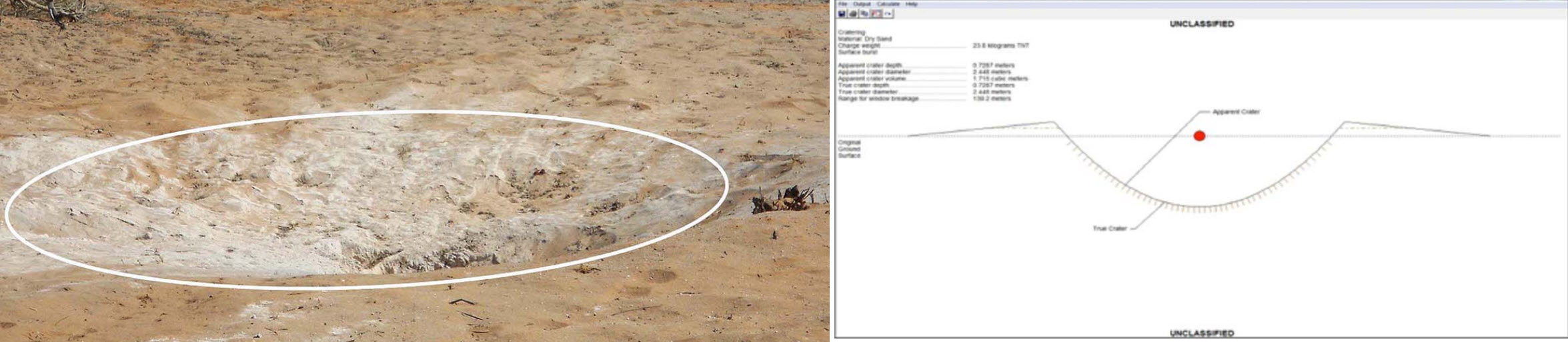
The formulae introduced above can be illustrated by comparing their predictions with documented examples of craters for which the munition (and thus, often, the explosive composition and NEW) are known. For example, a crater produced by a MK 84 2,000-pound-class air-delivered bomb, which was detonated using a C-4 explosive charge, can be seen in Figure 2. As noted, a typical MK 84 contains approximately 945 lb (429 kg) of Tritonal explosive which, together with 7.5 lb (3.4 kg) of C-4 explosive and accounting for their relative explosive performance, gives a total net explosive weight (NEW) of approximately 1,021 lb (463 kg) TNT equivalent. Plugging this value into the calculator returns an expected crater diameter of approximately 25 to 32 feet (7.6–9.8 m), and a depth of 6 to 8 feet (1.8–2.4 m) when accounting for different types of clay soil. This broadly accords with information recorded in DVIDS, which notes that the crater generated by the demolition was approximately 25 ft (7.6 m) in diameter, and 10 ft (3 m) deep. Whilst no single example can validate the model under all conditions, this test shows that the calculated estimate broadly accords with observed results. The discrepancy in crater depth likely results from the simplified estimation technique used in this introductory calculator. Crater depth is generally more sensitive than diameter to variables, including soil properties, moisture, and the precise conditions of detonation.
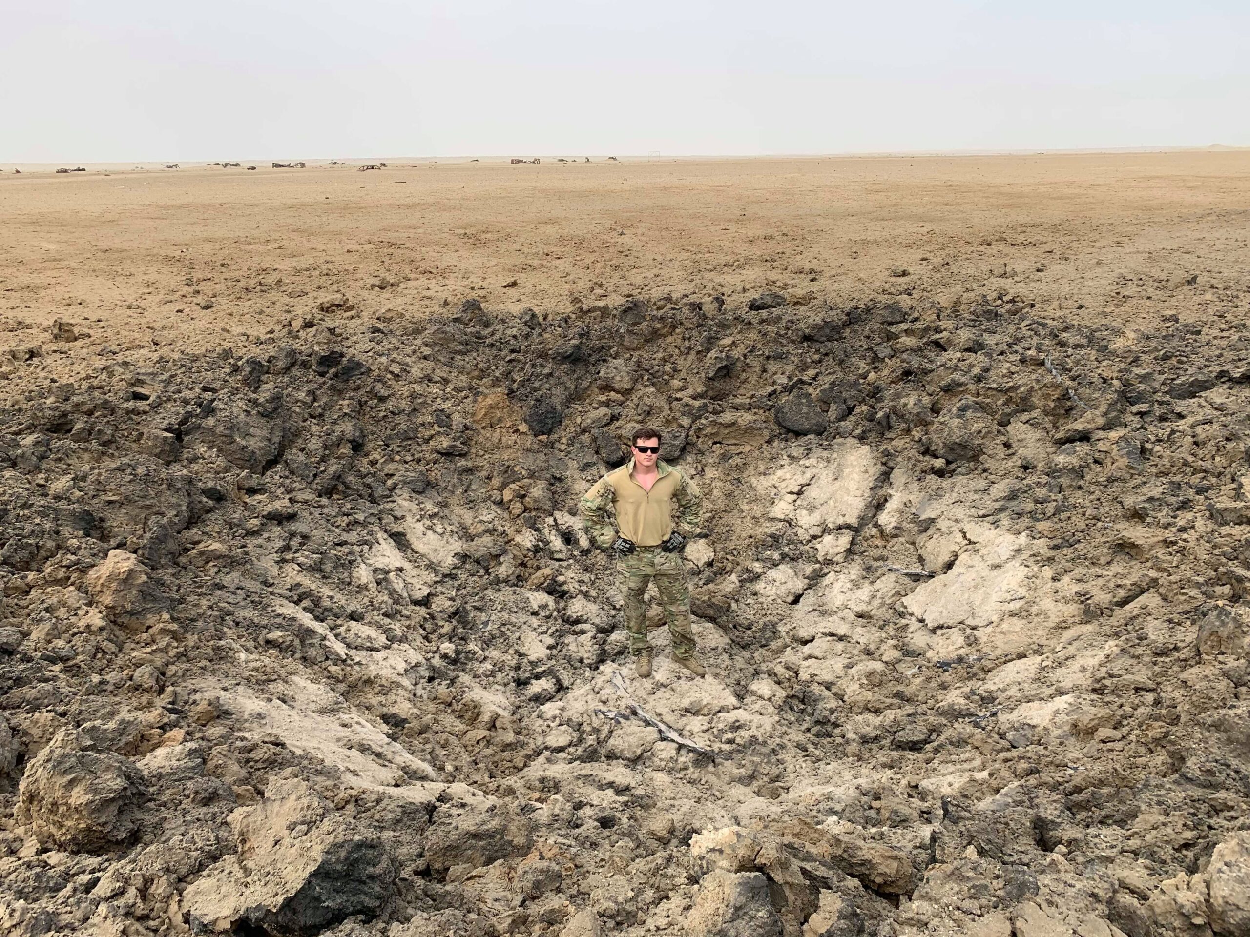
Table 3 – Nominal Crater Sizes for MK 80-series Bombs
| Bomb | Bomb weight class | Explosive Weight | Crater Width | Crater Depth |
| MK 82 | 500 lb | 87 kg (192 lb) | 4.6–10.7 m (15.1 – 35.1 ft) | 0.76–4.27 m (2.5 – 14 ft) |
| MK 83 | 1,000 lb | 201 kg (445 lb) | 6.1–13.7 m (20.0 – 44.9 ft) | 0.92–5.49 m (3.0–18 ft) |
| MK 84 | 2,000 lb | 428 kg (945 lb) | 7.6–18.3 m (24.9 – 60 ft) | 1.22–8.84 m (4 – 29 ft) |
| BLU-109 | 2,000 lb | 242 kg (535 lb) | Comparable to MK 83 | Comparable to MK 83 |
Crater analysis calculations generally assume a ‘simple’ or ‘general-purpose’ high explosive (blast) munition at or immediately below ground level. Whilst these calculations account for different explosive compositions and soil types, different types of explosive munitions (e.g., penetrating munitions), other types of explosive warheads (e.g., shaped charge), and specialised fuzing can significantly complicate matters. In some cases, other diagnostic techniques (such as an examination of fragmentation patterns or entry holes) may prove more fruitful than crater analysis.
If you are calculating the expected crater size from a munition, you should ensure that you are using the net explosive weight (NEW) rather than the overall weight of a munition. For example, penetrating munitions such as the BLU-109—a common fixture in modern conflict zones (often fitted with a Joint Direct Attack Munition (JDAM) guidance kit)—carry a smaller total amount of explosive material compared with general-purpose munitions of the same weight class. The BLU-109 is a 2,000-pound-class air-delivered bomb, but contains only 535 lb (243 kg) of explosives, compared with the 945 lb (429 kg) of the MK 84. As such, it is important to remember that the weight class of a munition is not directly correlated with the expected crater volume.
Height of Burst/Depth of Burial
One of the major factors that can complicate crater analysis is the position of the detonation relative to the ground surface (i.e., the height of burst or depth of burial of an explosive charge). Some munitions, including so-called ‘bunker buster’ air-delivered bombs like the BLU-109, are designed to penetrate into the ground or a structure before functioning; others are intended to detonate before striking the ground, to maximise fragmentation effects. Some munitions are fitted with fuzes that allow the operator to select the position of detonation. The proportion of explosive energy transferred into the ground is strongly influenced by the position of the detonation relative to the surface. A charge detonating above the ground will expend much of its energy expanding through the air, whereas a charge detonating on or below the surface transfers a greater proportion of its energy into the surrounding soil. Consequently, the same explosive charge can produce very different crater effects depending on whether it functions as an airburst, surface burst, or subsurface burst (‘buried charge’).
According to Explosives Engineering, a charge that detonates on the surface will impart approximately 33% of its explosive energy into the ground to form a crater, whereas a charge detonating at a height of approximately 2.5 charge radii above the surface will impart only about 1% of its energy into crater formation. This illustrates that even relatively small differences in height of burst can significantly affect crater size. Conversely, a charge buried below the surface can initially produce a larger crater as the surrounding soil provides greater confinement and improves the transfer of explosive energy into excavation. For example, one study of craters created by 120 mm mortar projectiles found that larger craters were most likely created by mortar projectiles that penetrated the earth, rather than detonating on the surface. However, this effect only occurs up to an optimum depth of burial, which varies according to charge size, explosive properties, soil conditions, and other factors. Beyond this depth, the explosion becomes increasingly contained by the surrounding material and may fail to produce a surface breach.
If a munition penetrates sufficiently deeply into the ground, the resulting buried detonation may not produce a breach of the surface. Instead, the overlying soil may subside to fill the cavity created by the underground blast, or a freestanding cavity may form without disturbing the ground surface (see Figure 3). Cooper (1996) reports that the optimum depth of burial for maximum crater formation occurs when the relationship between the net explosive weight (NEW), W (in lb), and the depth of burial, DOB (in ft), satisfies:
\[ \frac{W^{7/24}}{\mathrm{DOB}} \approx 0.3 \]
As this decreases to approximately 0.16–0.18, the explosion is expected to become fully contained within the soil, resulting in a subsidence crater or a freestanding underground cavity rather than a surface breach.
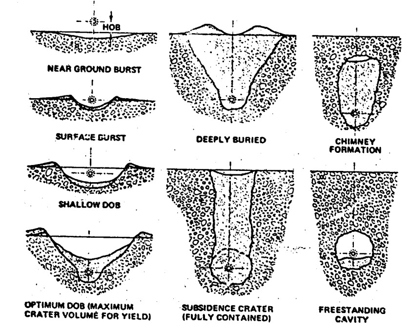
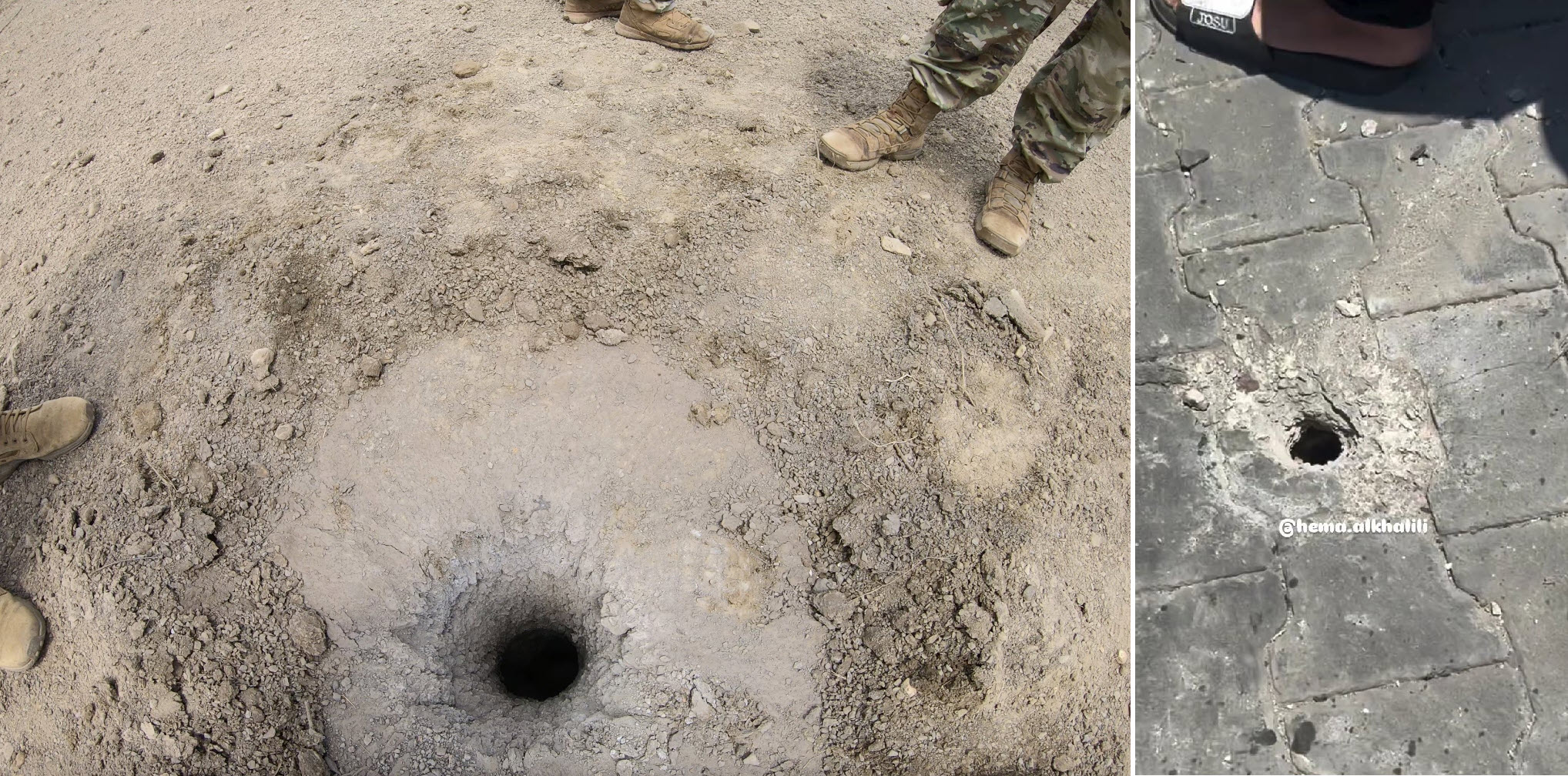
This helps explain why even large munitions with a significant NEW, such as air-delivered bombs, may only leave an entry hole where the munition penetrated into the ground, rather than generating a crater (see Figure 4). If a penetrating munition fails to function as intended, there may be even less disturbance to the topsoil.
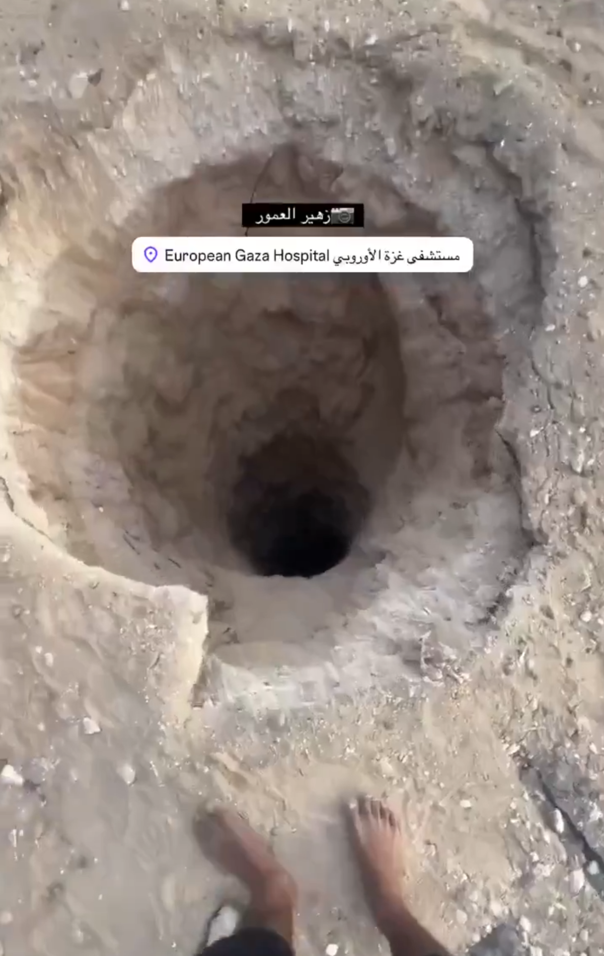
A MK 84 2,000-pound-class air-delivered bomb carrying 945 lb of Tritonal would need to penetrate about 47 ft (14.3 m) into the earth before detonation to result in a subsidence cavity or freestanding crater, rather than a typical crater. A smaller MK 82 500-pound-class bomb, which carries 192 lb (87 kg) of Tritonal, would need to penetrate about 29.5 feet (9 m). The BLU-109, with 535 lb (243 kg) of Tritonal, would need to penetrate about 40 ft (12.2 m). (Note that these general calculations do not account for voids, such as tunnels.)
Holes in a target surface may not necessarily be caused by the penetration of a munition, however. Similar (albeit typically smaller) damage is caused by munitions that use a shaped charge to create either a high-velocity metal jet (in the case of high explosive anti-tank, or HEAT, warheads) or an explosively formed penetrator (EFP). When these munitions explode at or near the surface, the shaped charge jet or EFP penetrates into the target surface, creating a relatively small hole (see Figure 5). These impact sites often bear distinctive features that can be analysed, and remnants of the functioned munition may also be located nearby.
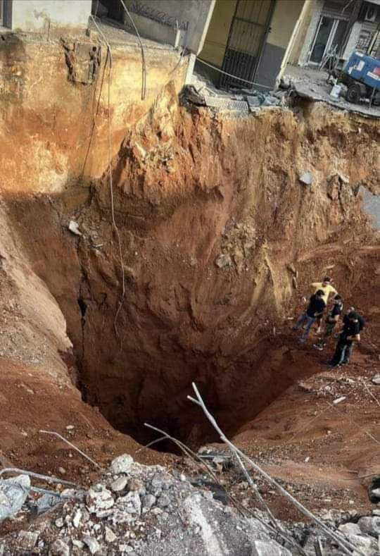
Multiple munitions may strike the same point, or very nearby, complicating assessment of a crater or overlapping craters. This can form crater systems of varying morphology based upon the types and sizes of munitions used, the local geology, and other factors. The 2024 Israeli strike that killed Hezbollah’s Secretary General Nasrallah, for example, saw multiple air-delivered bombs dropped on the same target to achieve deeper penetration into the ground, resulting in a crater that was significantly larger than one that would be created by a single BLU-109 bomb (see Figure 6). The morphology of a crater system like this cannot be interpreted using single-charge empirical relationships such as the calculator presented herein.
Determining Firing Point of Origin
It is clear, then, that the size and shape of a crater, together with accompanying physical evidence—such as fragmentation damage or munition remnants—can provide important information for investigators. In some cases, these can be used to identify the type, weight class, or calibre of the munition used. Estimating explosive charge weight is only one application of crater analysis, however. The geometry of a crater and the distribution of ejecta and fragmentation can also preserve information about a munition’s trajectory, allowing investigators to estimate the direction from which it was fired. Craters caused by artillery gun and mortar projectiles, as well as some rockets, are relatively small, and often feature distinct fragmentation patterns and crater shapes. Impacts that occur closer to a 90-degree angle will form more circular craters, while those munitions striking a flat surface at substantially lower angles will form more elliptical (oval-shaped) craters. On hard surfaces, such as asphalt or concrete, crater shapes and fragmentation patterns may be even more pronounced—even as the size of depth of a crater is reduced.
Where sufficiently distinct, these features can be used to determine the type of munition employed. If a model or calibre can be identified (often by assessing crater size, fragmentation patterns, and remnants), this can be considered with the ballistic trajectory and known range limitations of such munitions to identify a likely direction of fire (sometimes called ‘direction of gun’). A publicly available U.S. military artillery targeting manual contains a section on crater analysis which provides instructions for determining a firing point of origin. This section is intended to assist soldiers in identifying the firing direction of incoming artillery rounds, so that they can conduct counter-battery fire. (Similar techniques are outlined in non-public references, and taught on military courses.)
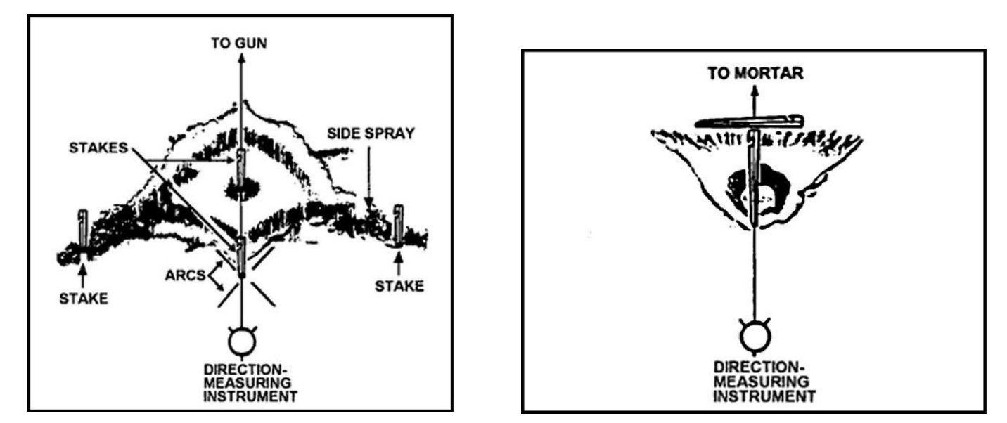
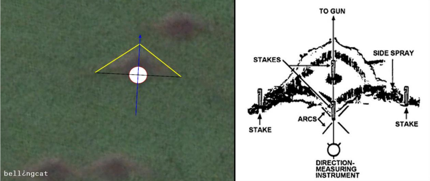
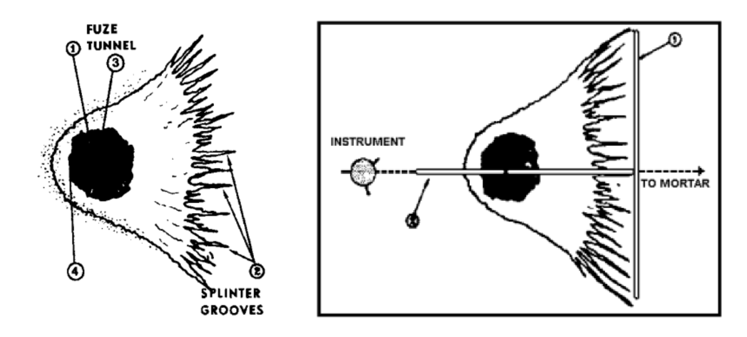
There are a number of techniques that can be used to determine firing point of origin from crater analysis. Whilst developed for use by personnel with physical access to the site, many of these can be applied if sufficiently high-quality imagery is available. For example, one typical method for determining the direction of a gun is by identifying a ‘fuze tunnel’ created in the crater as a result of the fuze being propelled into the ground in the direction of travel. However, remote crater analysis will generally be limited by image quality and the variety of available viewing angles, and this detail is often not captured. Remote crater analysis should be carefully applied in concert with other techniques. This article focuses on two methods (see Figure 7) that can often be applied to open-source imagery of projectile craters: the ‘side spray’ method for low-angle craters (artillery gun projectiles), and the ‘splinter groove’ method for high-angle craters (mortar projectiles).
Both of these methods work by identifying key characteristics of the crater to identify the general direction of the gun, then bisecting the crater as symmetrically as possible to give a more precise direction. The decision as to which method to apply is most often made on the basis of a morphological assessment of the crater, the form of which is affected by angle of impact. The angle of impact is typically 15 to 20 degrees for artillery gun projectiles, and 70 to 80 degrees for mortar projectiles. Craters formed by rockets can often be assessed using these methods, depending on the angle of impact, but vary more significantly between different types, models, and methods of attack. The earlier a crater is assessed after formation, and the more clearly defined it is, the more suitable it is for analysis. Assessing multiple craters, especially those some distance apart, can enable a more confident determination of the direction of the gun.
Side Spray Method
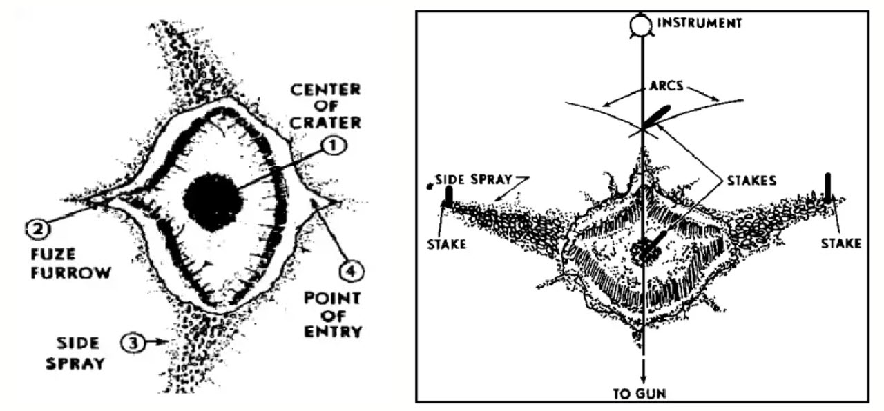
For low-angle impact craters, like those created by artillery gun projectiles, the detonation of a round forms an inner crater, before the momentum of the munition and the explosion carry the blast and fragmentation effect forward (away from the direction of the gun) and outward (towards the sides of the crater). ‘Nose spray’, which may include a distinctive ‘fuze furrow’ created by the fuze being propelled forward, often leaves a distinct pointed impression facing away from the direction of fire. The fragmentation effect reaching out to the side of the crater, known as ‘side spray’, together with the general shape of the crater (with nose spray), forms an ‘arrow’ pointing towards the origin of fire. Bisecting the crater along the point of this arrow indicates the direction to the gun (see Figures 8, 9 & 10).
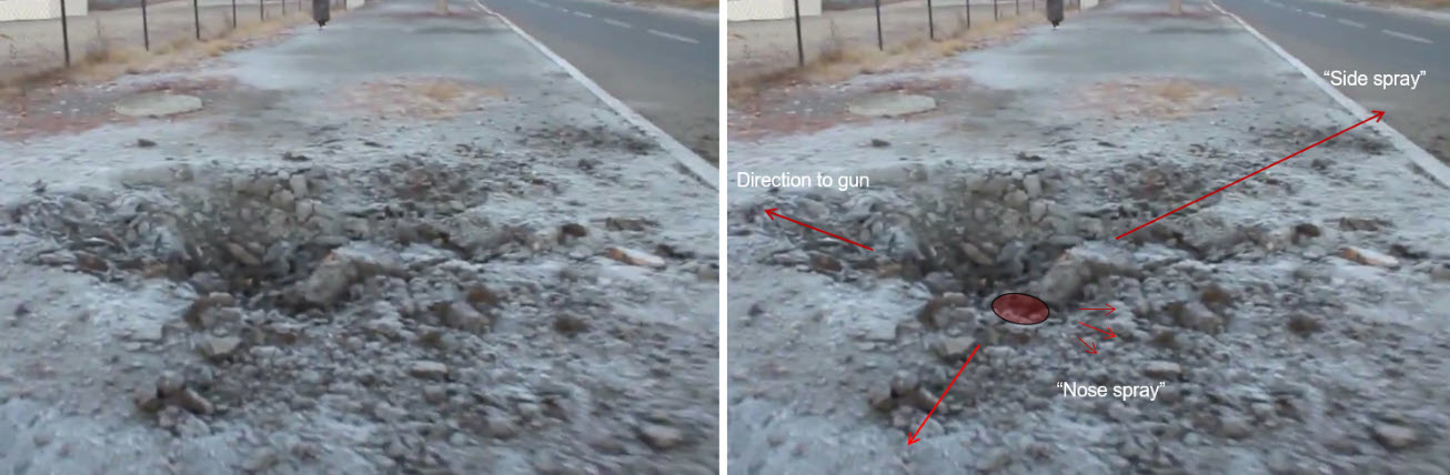
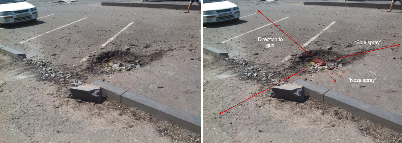
This method can also be applied, albeit often with reduced confidence, to suitable craters identified in satellite imagery. When examining satellite imagery in this way, analysis of multiple craters can greatly increase confidence. Bellingcat used this type of crater analysis to determine that artillery fired at Ukrainian forces in 2014 likely originated from artillery positions in Russia (see Figure 11).
Splinter Groove Method
For high-angle impact craters, particularly those associated with mortar projectiles, a similar method of bisecting the crater to determine the direction to the gun is used. The U.S. military manual describes the features of this type of crater:
“In a typical high-angle mortar crater, the turf at the forward edge (the direction away from the hostile mortar) is undercut. The rear edge of the crater is shorn of vegetation and grooved by splinters. When fresh, the crater is covered with loose earth, which must be carefully removed to disclose the firm burnt inner crater. The ground surrounding the crater is streaked by splinter grooves that radiate from the point of detonation. The ends of the splinter grooves on the rearward side are on an approximately straight line. This line is perpendicular to the horizontal trajectory of the round.”
To find the direction of gun or mortar using the splinter groove method, a line is drawn at the rearward side of the splinter grooves, and then bisected to determine the origin of fire (see Figure 12).
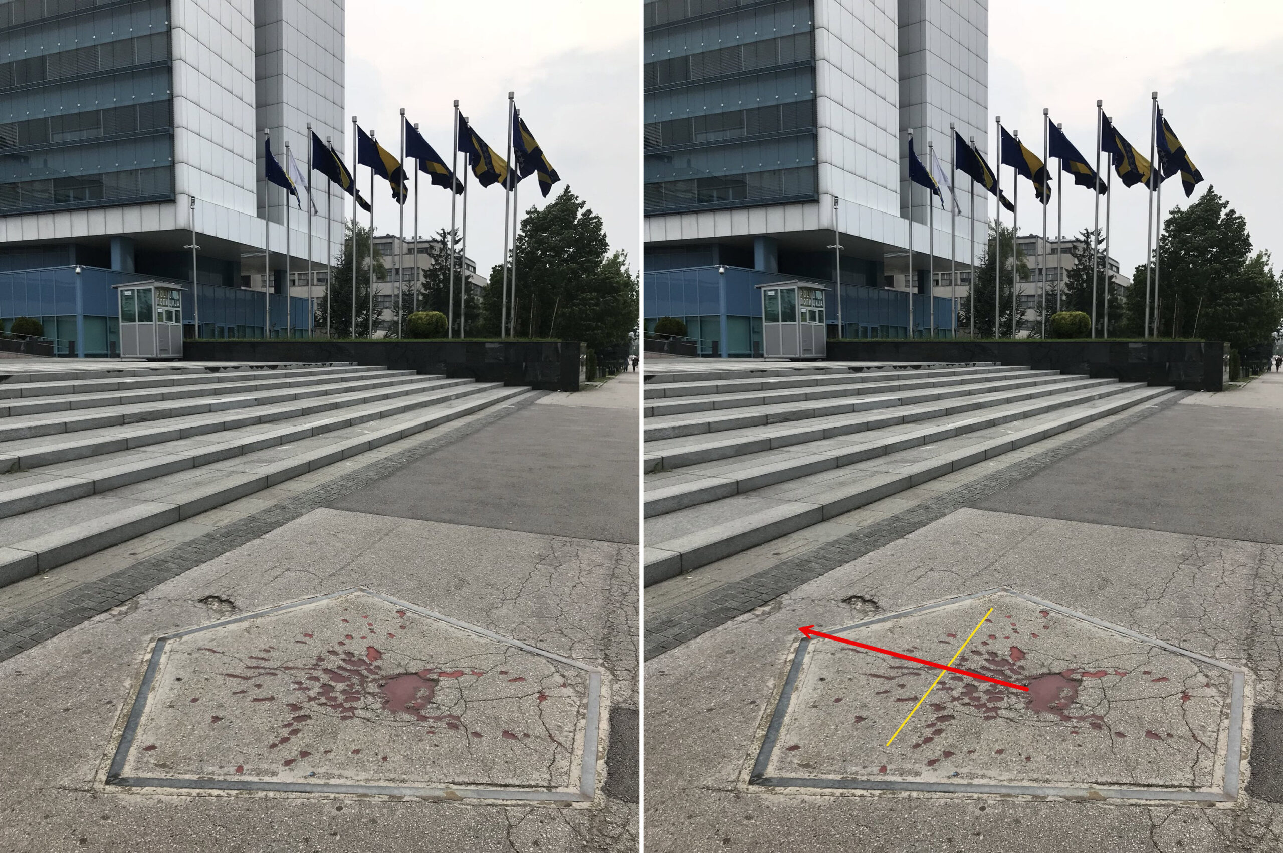
A high-angle mortar projectile impact preserved in Sarajevo can be seen in Figure 13. This example shows a mortar impact on concrete from Bosnian war, which years later can still be used to estimate the direction to the gun which fired it.
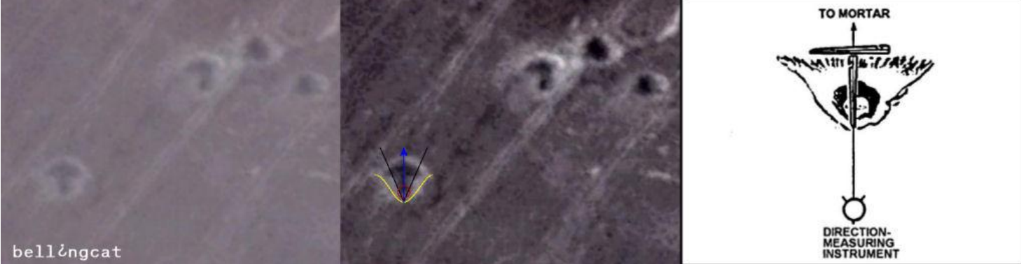
This method, like the side spray method, can be applied to suitable craters visible in satellite imagery (see Figure 14), with similar caveats.
Some munitions can create fragmentation patterns that may appear similar to splinter grooves, nose spray, or side spray used in assessing impact craters; an example can be seen in the Hellfire missile strike shown in Figure 15. Assessing the crater and fragmentation markings to confirm the damage is consistent with that expected from an impact crater is crucial.
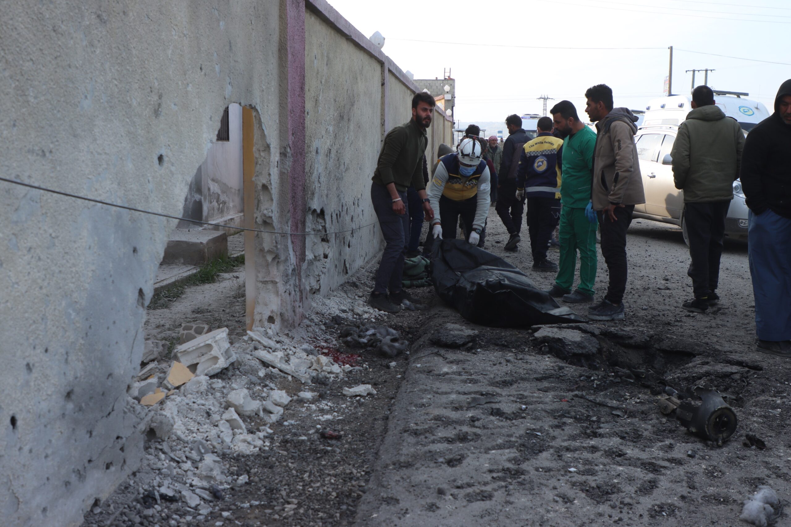
Once the direction of the gun is determined, the maximum range of a given weapon, or possible weapon, can be used to identify an area in which to search for the firing point. Weapons such as artillery guns and mortars, military positions, or burn scars may be visible on satellite imagery and can help identify the specific area from which weapons were fired. For example, the Yale Humanitarian Research Lab identified Norinco AH4 155 mm artillery guns on satellite imagery approximately 25 km northeast of El-Fasher, Sudan, following the shelling of the city in 2024. This was well within their maximum range. An example of various artillery platforms as seen in typical satellite imagery is shown in Figure 16.
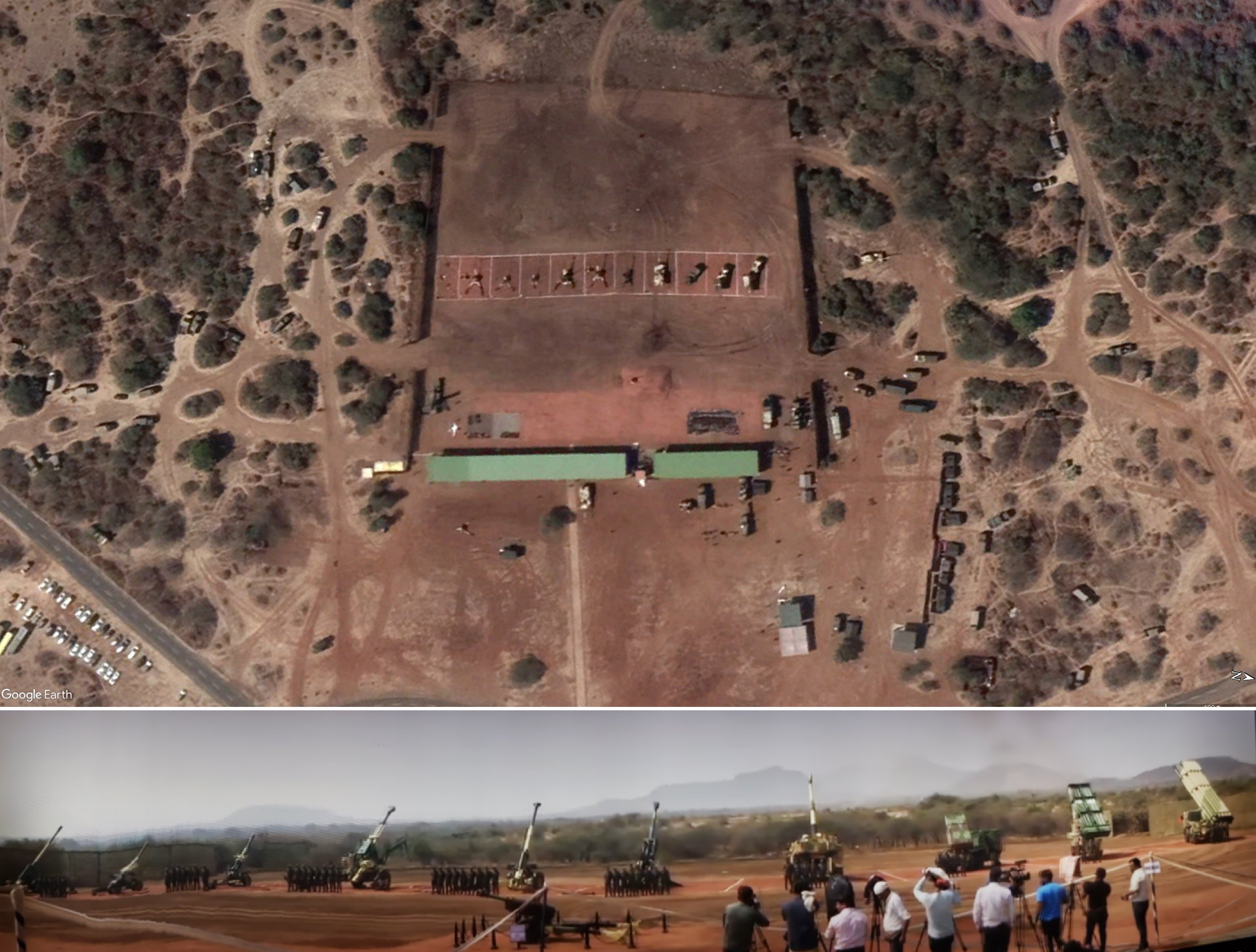
Crater analysis is a valuable investigative technique that can link observable physical evidence with the characteristics of a munition that produced it. Whilst this approach can provide key information about an incident—including estimates of explosive charge size, munition type, and, in some cases, direction of fire—it is just one component of a broader conflict damage assessment, and the wider investigation a CDA supports. The strongest conclusions will be reached when the results of crater analysis are considered alongside other sources of evidence, including physical forensic examination, fragmentation and ‘strike line’ analysis, witness testimony, geolocation and chronolocation, satellite imagery, and more. When crater analysis is combined with arms and munitions identification techniques, in particular, CDAs can be a powerful tool to support evidence-based attribution of attacks.
Sources
ARES (Armament Research Services). n.d. Conflict Materiel (CONMAT) Database. Confidential. Perth: ARES.
ARES (Armament Research Services) & Airwars. n.d. The Open Source Munitions Portal (OSMP). <osmp.ngo>.
Ball, Trevor & N.R. Jenzen-Jones. 2024. ‘Guidance Kits for Mark 80 Series Air-Delivered Bombs.’ The Hoplite (ARES company blog). <armamentresearch.com/guidance-kits-for-mark-80-series-air-delivered-bombs/>.
Bellingcat Investigation Team. 2015. ‘Bellingcat Report – Origin of Artillery Attacks on Ukrainian Military Positions in Eastern Ukraine Between 14 July 2014 and 8 August 2014.’ Bellingcat. <bellingcat.com/news/europe/2015/02/17/origin-of-artillery-attacks/>.
Cooper, Paul W. 1996. Explosives Engineering. Weinheim: Wiley-VCH.
Cooper, Paul W. & Stanley R. Kurowski. 1997. Introduction to the Technology of Explosives. Weinheim: Wiley-VCH.
Dexter, Richard M., Brian L. Hamshere & Ian J. Lochert. 2002. ‘Evaluation of an Alternative Grade of CXM-7 for Use in PBXN-109, The Explosive Fill for the Penguin ASM Warhead’. DSTO Systems Sciences Laboratory. Avaialble via: <apps.dtic.mil/sti/tr/pdf/ADA408346.pdf>.
Dullum, Ove S., Kenton Fulmer, N.R. Jenzen-Jones, Chris Lincoln-Jones & David Palacio. 2017. Indirect Fire: A Technical Analysis of the Employment, Accuracy, and Effects of Indirect-Fire Artillery Weapons. Perth: Armament Research Services (ARES). <armamentresearch.com/wp-content/uploads/2017/01/ARES-Special-Report-Indirect-Fire_web.pdf>.
Gildart, Robert C. 1994. ‘Countermortar’. The Field Artillery Journal (December).
Kinney, Gilbert Ford & Kenneth Judson Graham. 1985. Explosive Shocks in Air. Berlin: Springer. <link.springer.com/book/10.1007/978-3-642-86682-1>.
OrdTech Industries. n.d. ‘Mk84 2000 Lbs Aircraft Bomb’. OrdTech Industries. <ordtech-industries.com/mk84-2000-lbs-aircraft-bomb/>.
Smith, North. 1982. Testing Shaped Charges in Unfrozen and Frozen Silt in Alaska. Washington, D.C.: U.S. Army Corps of Engineers. Available via: <apps.dtic.mil/sti/pdfs/ADA113670.pdf>.
Strange, John N. & Allen D. Rooke Jr. 1988. Battlefield Dust From Exploding Munitions: Contribution By Cratering From Artillery and Mortar Projectiles. Washington, D.C.: Department of the Army. Available via: <apps.dtic.mil/sti/pdfs/ADA203028.pdf>.
TOI Staff. 2024. ‘Smoke and Ruins: A Look at the Wreckage at the Site of Nasrallah’s Assassination.’ The Times of Israel (29 September). <timesofisrael.com/smoke-and-ruins-at-the-site-of-nasrallahs-assassination/>.
United Nations Security Council. 2014. ‘Letter dated 7 February 2014 from the Chair of the Security Council Committee established pursuant to resolution 1591 (2005) concerning the Sudan addressed to the President of the Security Council’. S/2014/87 <https://www.securitycouncilreport.org/atf/cf/%7B65BFCF9B-6D27-4E9C-8CD3-CF6E4FF96FF9%7D/s_2014_87.pdf>.
U.S. Army Field Artillery School. 1992. Crater Analysis and Shell Reports. Washington, D.C.: Department of the Army.
U.S. Marine Corps. 2002. Tactics, Techniques, and Procedures for Field Artillery Target Acquisition. Washington, D.C.: Headquarters, U.S. Marine Corps. Available via: <govinfo.gov/content/pkg/GOVPUB-D214-PURL-gpo130684/pdf/GOVPUB-D214-PURL-gpo130684.pdf>.
Walsh, Marianne E., Charles M. Collins, Michael R. Walsh, Charles A. Ramsey, Susan Taylor, Susan R. Bigl, Ronald N. Bailey, Alan D. Hewitt & Mark Prieksat. 2008. Energetic Residues and Crater Geometries From the Firing of 120-mm High-Explosive Mortar Projectiles Into Eagle River Flats, June 2007. Washington, D.C.: U.S. Army Corps of Engineers. Available via: <apps.dtic.mil/sti/pdfs/ADA484240.pdf>.
Waters, Nick. 2018. ‘Who Attacked the Hodeidah Hospital? Examining Allegations the Saudi Coalition Bombed a Hospital in Yemen.’ Bellingcat. <bellingcat.com/news/middle-east/2018/08/09/attacked-hodeidah-hospital-examining-allegations-saudi-coalition-bombed-hospital-yemen/
Humanitarian Research Lab (HRL). 2024. Special Report: RSF Heavy Artillery in Range of Zamzam IDP Camp as Civilians Flee. New Haven: Yale School of Public Health HRL. <ysph.yale.edu/download-file/dccced7b-e41d-42d9-82a8-51a9b0eaa816/>.
Remember, all arms and munitions are dangerous. Treat all firearms as if they are loaded, and all munitions as if they are live, until you have personally confirmed otherwise. If you do not have specialist knowledge, never assume that arms or munitions are safe to handle until they have been inspected by a subject matter specialist. You should not approach, handle, move, operate, or modify arms and munitions unless explicitly trained to do so. If you encounter any unexploded ordnance (UXO) or explosive remnants of war (ERW), always remember the ‘ARMS’ acronym:
AVOID the area
RECORD all relevant information
MARK the area from a safe distance to warn others
SEEK assistance from the relevant authorities