For those seeking more detail on the complex interrelationship of the AN-94 self-loading rifle’s dual operating systems and unusual trigger mechanism, ARES Technical Specialist Jonathan Ferguson has developed a brief interpretation to clarify the key operating mechanics. Further and complementary detail may be found in the previous ARES post and in the original patent description and drawings – Ed.
AN-94 Operation in Detail
Jonathan Ferguson
Common Features (all firing modes)
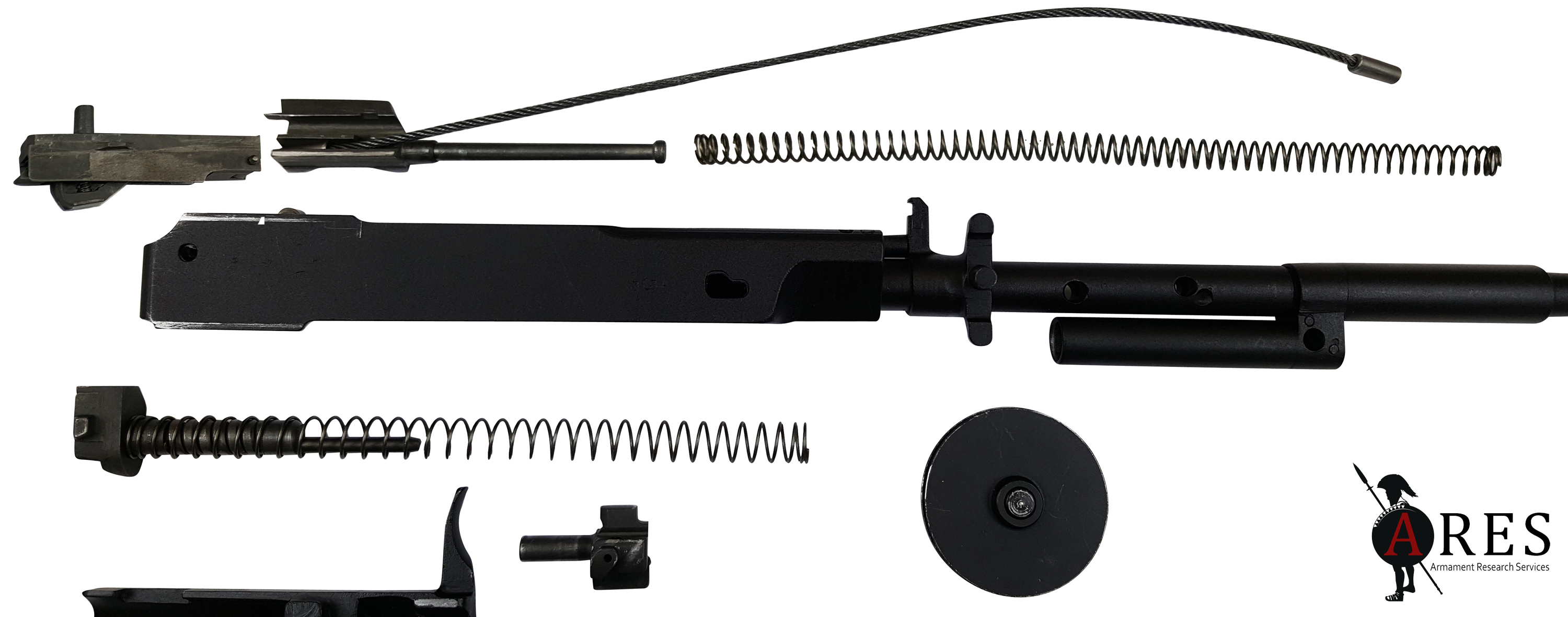
With a projectile travelling down the bore, the recoil-operated firing unit starts moving fractionally before the gas operated bolt and carrier, compressing the front buffer. The latter is driven by a long-stroke piston running inside the gas tube, which is located on the firing unit and concealed under the upper handguard. The carrier group, which has its own return spring, begins a normal gas operation cycle by extracting and ejecting the first fired case but, thanks to the counter-recoil pulley, also pushes a second cartridge into the feeding position on the follower at the same time. It then returns forwards, picking up this second cartridge and chambering it. At this point, with the firing unit almost at the rearward limit of its travel, the second cartridge is fired and the gas system again cycles the bolt and carrier. However, despite having reciprocated once already, the carrier group is still (overall) moving to the rear due to the ongoing recoil of the firing unit. The firing unit having moved further back by this point, the carrier moves further back within the outer receiver on this second cycle, even though it travels the same distance within the firing unit for both shots. In effect, the chamber has moved backwards, so the bolt carrier group must also move further to the rear. This is visible in high speed footage captured by Larry Vickers and his team (watch the bolt handle). A fraction of a second later, both mechanisms reach the rear of the receiver together, and at the same time, thanks to the pulley, another cartridge is being pushed onto the secondary follower by the appropriately-named ‘pusher’. First the bolt carrier, and then firing unit return to their forward positions, and the next cartridge is picked up from the follower and chambered.
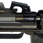
With the bolt locked into the firing unit, the firing pin is shrouded by the bolt carrier, protecting it from out of battery discharge. On engagement with the barrel extension the bolt is pushed back, protruding its rear from the carrier and putting the back of the firing pin in contact with the closed hammer. This system has been described as ‘slam-fire’, but this firing pin safety system means that this is not quite accurate. The firing pin cannot reach the primer until the bolt is fully locked. This locked-together mode of operation only occurs on the second shot of burst or automatic fire, when the selector is set accordingly. Detail of the trigger mechanism and its three modes follows below;
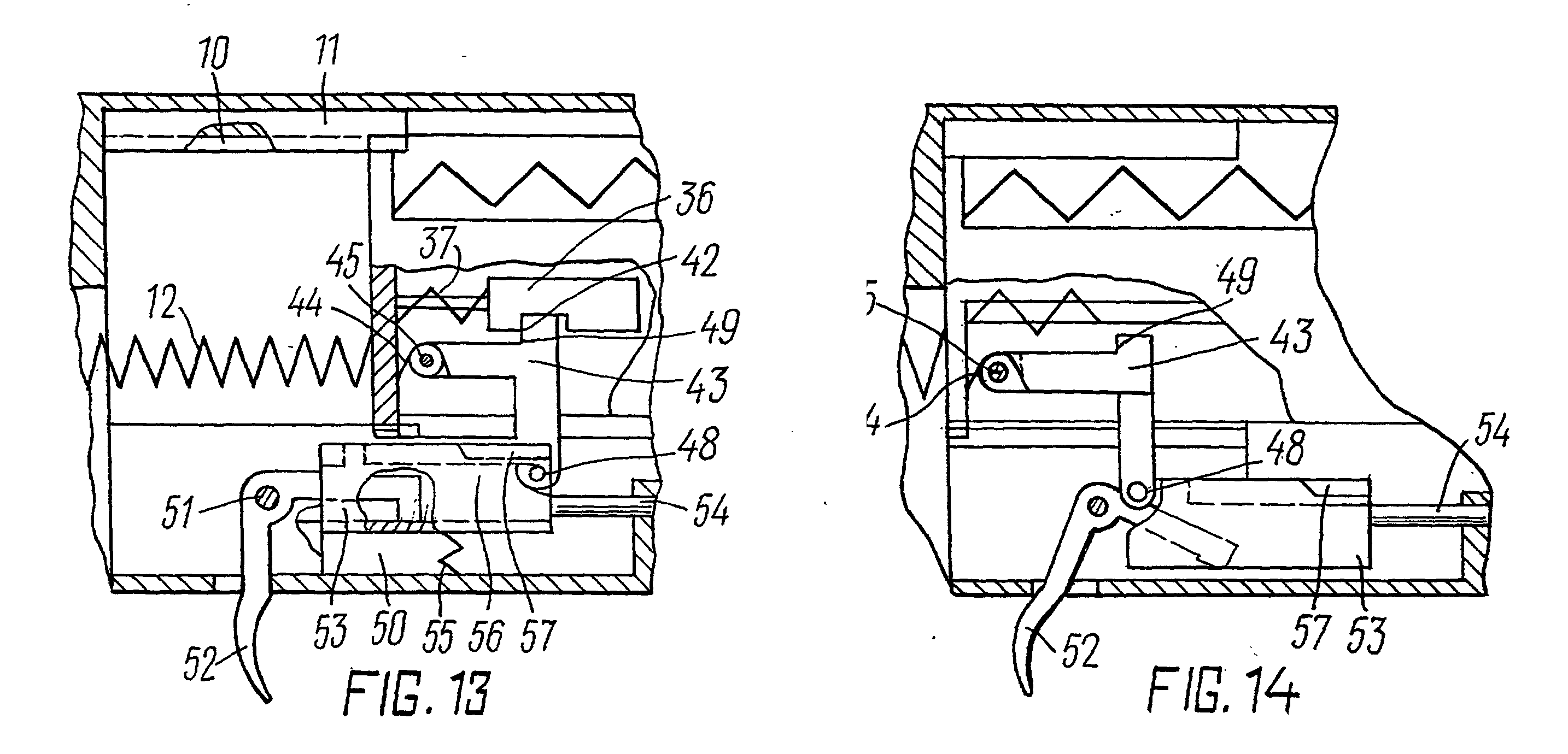
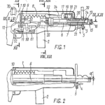
The interrelationship of the trigger (52), disconnector pawl (48), ‘tripper’ (trigger plate) (53), sear (43), and hammer. In the top drawing (with the weapon in battery) the pawl (48) is positioned under the ‘short cam’ of the trigger plate, but is actually engaged with the ‘long cam’ that runs just beneath it, ready for a semi-automatic shot. In the bottom image (with the weapon in full recoil) the trigger plate has been pressed down by the trigger, pulling the pawl and sear down and releasing the hammer. The pawl has then slid all the way to the rear of the trigger plate and out from under the ‘long cam’ (shown as a dotted line on the trigger plate).
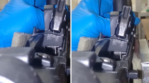
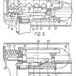
These images show the means by which the trigger is reset in all three modes of fire, and also how the sear is tripped in automatic fire. NB In this case the trigger frame is slid all the way forward as per semi-automatic fire, but the same mechanical relationship applies on slow rate automatic fire where the sear is tripped when the firing unit returns forward and the pawl encounters the same ‘short cam’ (albeit in automatic mode, the trigger frame is positioned further back when this occurs). In the left hand image, the trigger has been pulled and the pawl plunger attached to the sear is being pulled downwards by the ‘short cam’ on the front of the trigger frame, releasing the hammer. In the right hand picture, the trigger has been released, pivoting the trigger frame upward and allowing the pawl to pop back out under spring tension and sit under the ‘long cam’. In this reset position the trigger may be pulled for another shot.
Semi-automatic mode
With the selector switch slid all the way to the front and the trigger pulled, the weapon cycles as detailed above. As it travels rearwards, the pawl (#48 on the patent drawings) attached to the sear is permitted to slip off the rear of the shelf (‘long cam’, #56) on the trigger plate (as seen at 00:50 seconds into this helpful animation), quickly disconnecting the trigger from the sear. The hammer, which has been automatically locked into the bolt carrier when it fired the cartridge, recoils with the carrier, and strikes the top of the sear. This not only re-cocks it, but pushes it sideways, unlocking it from the carrier for a second semi-automatic shot. The carrier is then free to return home within the firing unit, before the firing unit itself starts to move forwards again, with the bolt closed and locked. The pawl then meets the trigger plate again, and is pushed inwards by it. This allows it to pass forwards along the outer edge of the ‘long cam’ (56) on the trigger plate. If the trigger remains held, the pawl (48) stays pressed in and out of engagement. When the trigger is released, the pawl can pop back out underneath this shelf, ready to be pulled down again for a second shot. This is how trigger reset is achieved.
Burst Mode
Note: the first two shots in Automatic Mode also take effect as follows.
Prior to firing the first shot of a burst, the pawl (48) starts out behind the front angled projection (‘short cam’, #57) of the trigger plate. On the first shot, the pawl travels rearwards along the trigger plate as the firing unit recoils, and as in the other modes, it slips off the rear of the ‘long cam’. Importantly, however, it does not achieve this until the first shot has been fired. The middle position delays the trigger reset long enough for the bolt and carrier to complete the first cycle within the firing unit. Effectively, the trigger is pulled, the first shot is fired, and the firing unit and bolt/carrier both start travelling backwards. By the time the sear travels backwards far enough to slip off the back of the trigger plate, the bolt, locked into the carrier, has overridden it and is on its way into battery, where it fires the second shot.
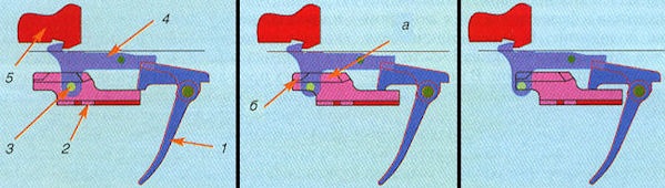
The initial relative positions of (1) the trigger, (2) the trigger plate, (3) the pawl, (4) the sear and (5) the hammer. Left to right: semi-automatic, two-round burst, and automatic firing modes.
The diagram showing the relative starting position of the pawl and trigger plate is useful and yet potentially misleading, since at the end of its return, the pawl now stops in line with the ‘short cam’ (57) on the front of the trigger plate, which projects further out than the continuous shelf (56). Provided the trigger is held, this ‘short cam’ holds the pawl, and therefore the sear, down; this, in turn, allows the hammer to remain locked to the bolt carrier, and the second shot to be fired when the bolt carrier has returned forward, but just before the firing unit reaches the rearward most position of its travel. This is sometimes referred to as ‘slam-fire’, but in fact as described above, a firing pin safety prevents the hammer from being released until the bolt has fully locked. At this point the pawl slips off the back of the ‘long cam’ (56) and finally disconnects. The trigger is released, and the pawl – also a plunger – is pressed in and resets for the next burst.
This is the most confusing aspect of the operation of the AN-94. In lieu of an animation of burst fire, see the semi-auto equivalent here (and the photo below under ‘Automatic’). This time index represents the end of the return forward stroke of the sear in semi-automatic. The picture would be almost identical in burst mode, with two crucial differences. Firstly, the trigger plate (marked in yellow) is slid slightly forwards, just shy of being centrally aligned with the round pin of the cross-bolt safety. This places the pawl directly beneath the front projection on the trigger plate, where trigger pressure keeps it down and out of the way. Because the pawl cannot slip off the back of the trigger plate’s ‘long cam’ shelf, the sear is not pulled downward, and the hammer is not released. The second major difference from the animation at that time index is therefore that the hammer would appear still locked into the bolt carrier, ready to fly forward with it to fire the second shot of the burst as described above, and before the firing unit hits the rear of the receiver.
Automatic
Slid all the way to the rear, the pawl (48) cannot slip off the ‘long cam’ of the trigger plate until two shots have been fired as per burst mode above. The rifle then shifts into 600 rpm automatic fire. You can see the shift occur in the sequence of fire shown at 01:31 in this Larry Vickers video. With the pawl held down by the trigger plate for even longer than in burst mode, the sear is also retained, and the hammer remains locked to the bolt carrier. As a result, the second shot is fired at the high rate as per two round burst mode, that is, just before the firing unit hits the rear of travel. With the trigger held down and the firing unit continuing to move rearward, the plunger finally travels far enough back to slip off the back of the selector and resets, catching the hammer on the next return stroke.
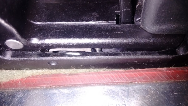
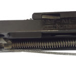
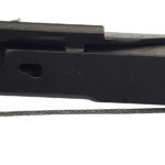
The pawl plunger as it slips off the back of the ‘long cam’ on the trigger plate, which occurs at the rearward stroke of the cycle in automatic mode. It is not easy to see, but without a cutaway, this is the only way to observe the actual operation of the AN-94 trigger mechanism. The light grey selector plate is visible at centre-left, just in front of the darker grey pawl plunger.
On the forward stroke, because the trigger plate is so far forward, the plunger is now able to slide all the way to the laterally projecting shelf (57 on the patent drawings) on the front of the trigger plate, where an angled surface on the rear allows it to pop back out, just before it reaches its fully forward position. It is now popped back out and positioned under the flat front projection on the trigger plate, meaning that provided the trigger remains held and there is ammunition in the magazine, the hammer is automatically tripped as the bolt closes.
Safety Catch
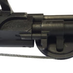
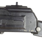
When the cross-bolt safety is pushed to ‘П’, a projection under the trigger plate prevents the latter from tilting and therefore the trigger from moving. In turn, because the trigger cannot move, its nose remains in place in a notch cut into the lower right corner of the firing unit, physically barring it from moving further back than a couple of millimetres unless the trigger is pulled. Thus even with the safety disengaged, this prevents the weapon being inadvertently placed out of battery by an environmental obstruction (such as cover or a firing port) or by the body of an enemy.
The wedge-shaped component on the front of the trigger plate runs in a groove on the underside of the pusher. When the safety is engaged, this wedge is pushed into a slot in the pusher, preventing it from moving. Because this is connected via the cable to the carrier, the carrier is also unable to move. Thus the weapon is prevented from being cocked, in a parallel to the uppermost position on the AK’s much simpler selector/safety lever (albeit the latter permits ‘press checks’, and the AN does not).
Hopefully this addresses any detailed queries that readers may have about this unique cycle of operation, at once complex and elegant in its execution.


Special thanks to the National Firearms Centre at the Royal Armouries, who graciously allowed us access to their world-class collection for this and other videos and photos.
Note: whilst the AN-94 in the Royal Armouries’ collection is a factory-made inert (MMG) example, as shown in the video and images here, ARES staff had access to a ‘live’ example from another confidential collection. This example could not be photographed for security reasons.
This article supplements an earlier instalment examining the AN-94 on The Hoplite, which examines the AN-94 in more general terms.
Remember, all arms and munitions are dangerous. Treat all firearms as if they are loaded, and all munitions as if they are live, until you have personally confirmed otherwise. If you do not have specialist knowledge, never assume that arms or munitions are safe to handle until they have been inspected by a subject matter specialist. You should not approach, handle, move, operate, or modify arms and munitions unless explicitly trained to do so. If you encounter any unexploded ordnance (UXO) or explosive remnants of war (ERW), always remember the ‘ARMS’ acronym:
AVOID the area
RECORD all relevant information
MARK the area to warn others
SEEK assistance from the relevant authorities